Just a few weeks ago, I decided to get back into my old hobby, amateur astronomy. I spoke to old astronomy friends to get some tips in buying an ultra-portable telescope and mount. This led me to Skywatcher's AZ-GTI mount and a 127cm Maksutov Cassegrain telescope. I bought a kit online which arrived in just a couple of days. I knew this mount is an alt-az mount but then my friend told me this can be converted to an equatorial mount, and be used for some basic astrophotography. I looked up online and found that, indeed, some people are using this mount in equatorial mode by putting it on a wedge and changing the firmware. I bought the wedge and the counterweight after watching this youtube video.
The wedge and the mount arrived in a week and this is when I found the problem. The whole setup looks cool and very compact. But the problems is, I can't configure it to my location's latitude. I am in a city that is only 1.4 degrees north of the equator. The mount hits the base of the wedge starting at 7 degrees. But I needed 1.4 degrees.
The review videos I watched online was done by people living in Canada or the USA which is far up in the northern hemisphere. So they do not have this problem.
Though I found people talking about the exact same problem, I never really found a real solution. I guess there is not a lot of people in the low latitude countries who bought this mount and wedge. So I decided to fix this myself. As an Agile practitioner, I solve problems iteratively.
Iteration 1
In the first iteration, I tried flipping the pinion gear of the wedge so that the dovetail is facing the opposite side. It somehow fixed the original problem. But it also created a new one. Some bolts are in an odd position and difficult to access, like the altitude adjuster. Also, the centre of gravity is now too far off the centre. It could actually tip the tripod over and could break your precious telescope.
Iteration 2
In the second iteration, I designed and 3d printed a wedge that will replace the Skywatcher wedge. The objective is to test the feasibility first and see if the plastic can hold the weight. I designed a very simple L bracket pre-configured angle of 91.4 degrees. This will give me a fixed altitude of 1.4 degrees.
I printed it at 40% honeycomb infill at a slightly higher temperature and higher extrusion rate for stronger layer adhesion. The printing process took 34 hours.
Although it looks cool, and it shows that it can handle the load, there are some problems with the design.
Problems / Lessons learned
- The main problem was that this 40% semi-hollow plastic shell flexes when there is a load. And when it does, that 1.44 degrees of altitude is lost and sometimes points below the horizon depending on the position of the telescope.
- The second problem was that you cannot adjust the azimuth so it's very difficult to polar-align especially when you cannot see Polaris.
- And lastly, the power adapter port is no longer accessible at a certain Right-Ascension angle. I forgot to take this into account while designing.
Iteration 3
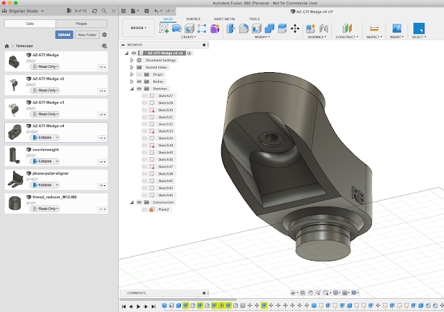
Based on what I learned from the second iteration, this Iteration was a complete pivot from the second. I decided to reuse the Skywatcher's wedge instead of replacing it so that I still have an azimuth adjuster. The objective this time was not to replace the wedge with a 3d printed one but to help that wedge alleviate the stress of very low latitude configuration. So I designed an extension of that wedge. This extension will tilt the wedge at 12 degrees angle and also move the wedge's mount point off centre, just enough to give room for the counterweight before hitting the tripod legs. This will give a better centre of gravity. And because of the 12 degrees offset, to achieve a 1.4 degrees altitude, the mount will just have to be configured at 13.4 degrees position, which is above the 7 degrees limit.
I printed this solid (100% infill) with a yellow PLA plastic that I already have. The printing process took almost 20 hours to complete. The result is amazing! It's very strong and heavy. It weighs almost a kilogram.
Problems / Lessons Learned
Although this iteration has proven that the new design works and the result is amazing and almost perfect, there are still very minor issues that need fixing.
- The colour is Yellow, does not fit with the Skywatcher's colour palette. This just because that's the only available filament I had at the time of printing.
- The thumbscrews at the bottom are quite difficult to tighten with your thumb. Because the gap between the thumb screw knobs and the base of the wedge extension is too tight as shown in the following image.
With these minor problems, I decided to do another iteration with more experimentation.
Iteration 4
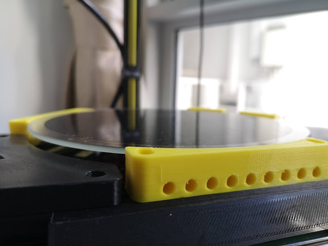
In this iteration, apart from fixing the Iteration 3 issues, I also experimented with a different material, ABS, an oil-based plastic. This is a slightly stronger material than what I usually use in 3d printing. This material also does not decompose. I have not tried printing with this material before. And, to be able to print with this material, I had to modify my printer by adding a heater at the print bed. This is required to print this material. So as extra work in this iteration, I hacked my 3d printer. I stuck a silicon heater to the glass print bed, installed a relay module and updated the firmware.
But this has led to a failed print. The material has warped significantly even though the bed is heated. It seems that the bed temperature settings were not set correctly.
In this iteration, I also tweaked the printing configuration, changed the
nozzle temperature, increased the print bed temperature to 110 degrees
Celsius and picked a slower printing speed. The print has less warping but after just 2 hours of printing, strange issues came up. There were layer shifting issues, and about 3 hours into the process, the printer crashed. The motherboard overheated and went into thermal shutdown and resets itself leaving me with unfinished print. The layer shifting can also be explained by overheating.
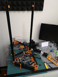
This iteration is a failure but it surfaced an issue with my 3d printer. I changed the design of the print bed of my 3d printer so that it leaves a gap where hot air can escape from the bottom of the print bed where the motherboard is.
The design change worked well. The printer no longer overheats. I tried a couple of huge prints without overheating issues. So I'm ready to try again.
Iteration 5
In this iteration, since the printer design is fixed, I tried again printing in ABS. There is less warping but there are layer adhesion problems. There are cracks in the print. I think I was still printing too fast. Or perhaps I should have enclosed the printer to give a uniform temperature across the layers.
The resulting print was indeed super strong, but with ugly looks and many cracks all over.
Iteration 6
I decided I had enough of ABS printing. So I bought a white PLA filament instead. I adjusted the design to fix the thumb screws gap. Added an embossed branding. Printed with a little over extrusion to make sure it doesn't leave any gaps between layers and ensures a stronger layer bond.
And here's the final result with the wedge and the AZ-GTI mount attached to it.
I'm happy with the final result and decided that this is the final version. Overall, I spent around $40 on filaments, few hours of CAD design, about a total of 40 hours of overnight printing. But the result is worth it. All problems are now solved. It looks cool and blends in very well with the Skywatcher colours. The only thing that worries me now is that in the next few years, PLA, the material I used, will start to degrade and eventually decompose especially when exposed outdoors. But I guess will deal with that in the next few years.
For anyone who has the same problem with AZ-GTi mounts in equatorial mode at low latitudes, feel free to download the 3d model STL file and print it yourself. Save yourself of the troubles I had.
You can get the STL file here --> https://github.com/rossbrigoli/az-gti-low-lat-adapter
Here are my print settings.
- Filament - 3d-aura PLA Extreme (super strong PLA)
- Nozzle diameter - 0.4mm
- Layer height - 0.2mm
- Infill - 100% solid
- Printed support - Yes
- Bed temperature - 70 deg C
- Nozzle temperature - 210 deg C
- The print speed at 120mm per second
- Printing orientation for maximum tension strength as per below:
Happy 3d printing!


